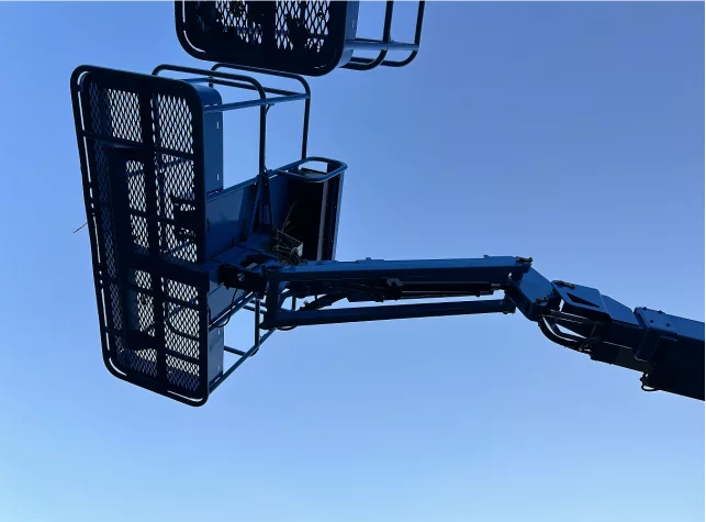
The boom lift aerial work platform, as a classic aerial work equipment suitable for indoor and outdoor multi-point operations, is renowned for its excellent ductility, heavy load capacity, strong power, easy maintenance, and high energy efficiency. It has a wide range of applications in the field of station venue operations. To make it easier for customers to use the boom lift aerial work platform.
The following will take JLG boom lift aerial work platform as an example to explain how to operate the boom lift aerial work platform correctly, as well as some precautions for operating the boom lift aerial work platform.
Related Reading: How To Operate The Scissor Lift?
Operation diagram of articulated boom lift
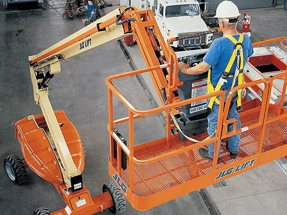
To operate articulated boom lift, the first step is to understand the various buttons of the aerial work platform, and equip the end of the telescopic and rotating arms of the articulated boom lift vehicle with a self-propelled hydraulic lifting device for the work platform. The main operator control station is located on the platform, as shown in Figure 1.
The operator can use this control station to drive and turn the articulated aerial vehicle forward or backward. The operator can raise or lower the upper and lower arms of the boom, or rotate the boom to the left or right. The standard boom rotates 360 degrees to the left and right of the storage position.

Figure 1.
The articulated boom lift aerial work platform ground control station, as shown in Figure 2, can be changed to ground control when the platform control station fails. Ground control can operate the lifting and rotating actions of the boom, used to lower the platform to the ground in emergencies when the operator on the platform is unable to operate. Ground control can also be used for pre-start checks.

Figure 2
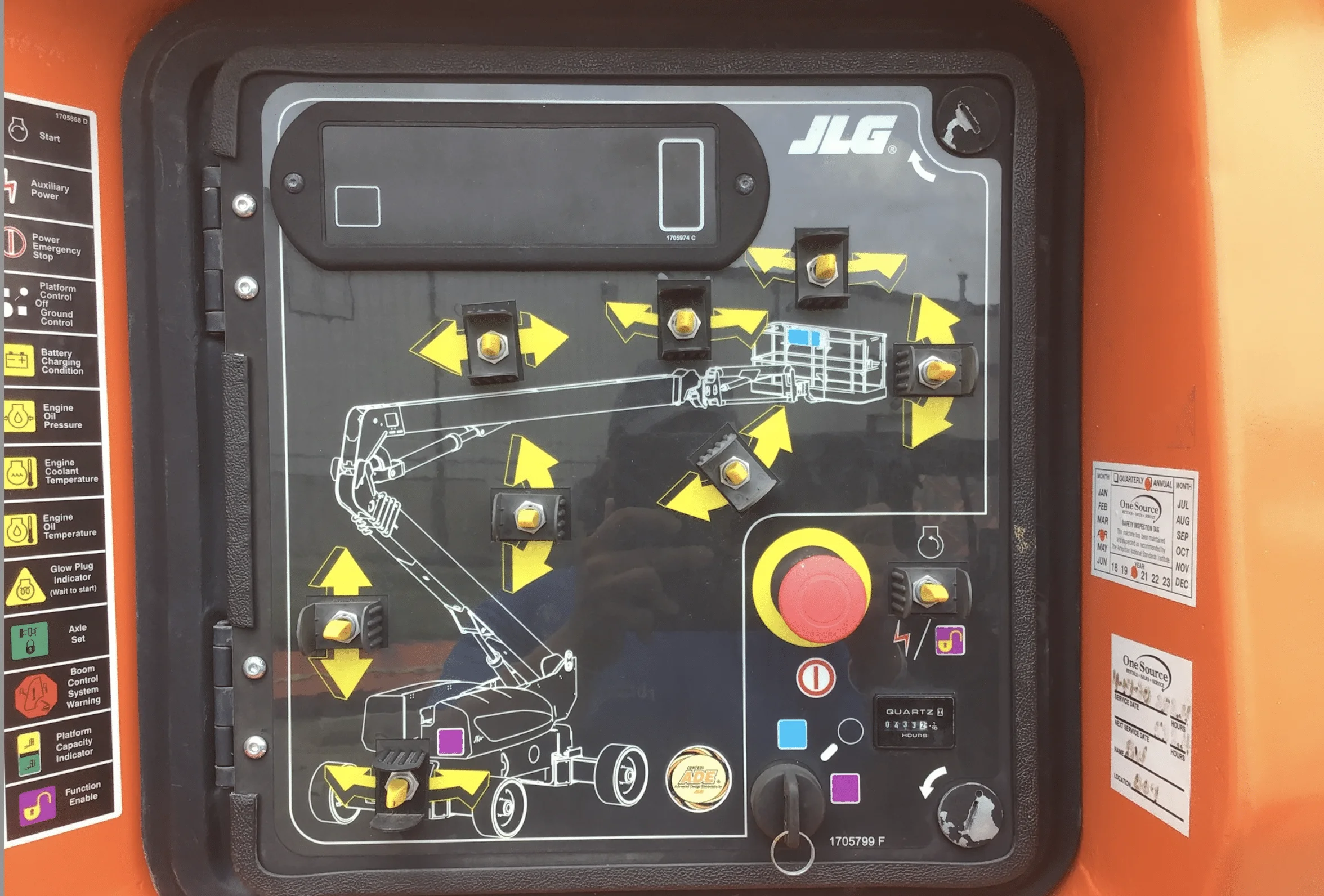
Ground control station for articulated boom lift
The boom lifting, rotation, platform leveling, boom extension, platform rotation, auxiliary power supply, tower arm extension, tower arm lifting, and forearm control switches are spring-loaded and will automatically return to the neutral (closed) position when released.
If equipped with a function authorization switch, this switch must be held down to operate functions such as boom extension, tower boom lifting, turntable rotation, boom lifting, jib lifting, platform horizontal positioning, and platform rotation. The following is a detailed introduction to each module:
1. Platform rotation
When placed in the left or right position, the platform rotation control switch can provide platform rotation.
2. Platform leveling
Allow the operator to adjust the 3-position switch of the automatic self leveling system. This switch is used to adjust the platform level in situations similar to uphill/downhill. The platform leveling function can only be used for minor leveling of the platform. Incorrect use may cause the load or personnel to move or fall. Violating this warning may result in death or serious injury.
3. forearm (if equipped)
When the forearm control switch is in the up or down position, it provides the function of raising or lowering the forearm, respectively.
4. Power/emergency stop switch
Two red mushroom switches, when pulled out (ON), can provide power to the platform/ground selection switch. When pressed (OFF), the power to the platform/ground selection switch will be turned off. When the power/emergency stop switch is in the “ON” position and the engine is not running, the alarm will sound and display the ignition switch as “ON”. When shutting down, the main control/emergency stop switch must be switched to the “OFF” position to prevent battery discharge.
5. Engine start/auxiliary power switch or engine start/auxiliary power switch/function authorization
When starting the engine of the articulated boom lift high-altitude work vehicle, keep the switch “up” until the engine starts. If you want to use an auxiliary power supply, this switch should always be kept “down” during the use of the auxiliary pump.
The auxiliary power supply can only be used when the engine is not running. If equipped with an authorization switch, the authorization switch must remain “down” during engine operation in order to activate all boom controls. The auxiliary power supply only operates without engine oil pressure and is disabled when the engine is running.
Due to the much smaller supply flow of hydraulic oil, the operation of various functions will be slower than normal. When using an auxiliary power supply, do not operate more than one function at a time. (Synchronous operation may cause overload of the auxiliary pump.)
6. Tower arm extension and retraction
When the tower arm telescopic control switch is placed in the IN or OUT position, it can control the extension and retraction of the boom. This function only works when the tower arm is fully raised (raised). To avoid overturning and serious injury, do not operate a articulated boom lift high-altitude work vehicle if the tower arm lifting and telescopic functions are not operated in the above order.
7. Timer
A timer installed at the bottom of the ground control box records the duration of use and engine operation of the articulated boom lift aerial work vehicle. By connecting the oil pressure circuit of the engine, only the time of engine operation is recorded. The maximum value of the timer is 9999.9 hours and cannot be reset to zero.
8. Platform/ground selection switch
When the 3-position key-operated switch is turned to the “platform” position, it will provide power to the platform console. When the switch key is in the “ground” position, the platform power will be turned off, and only ground control can operate. When the platform/ground selection switch is in the middle position, the power supply to the control devices of both operating stations is turned off.
9. Rotation control
When the rotary control switch is placed in the “right” or “left” position, it can provide 360 degree continuous turntable rotation. When operating the boom, ensure that there are no personnel around or below the platform.
If any control handle or toggle switch that controls the platform action does not return to the function off (OFF) position after being released, to avoid serious injury, do not operate the curved arm high-altitude work vehicle. To avoid overturning and serious injury, do not operate a curved arm high-altitude work vehicle if the tower arm lifting and telescopic functions are not operated in the above order.
10. Tower arm lifting and lowering
When the tower arm lifting control switch is placed in the down or down position, it can control the lifting and lowering of the tower arm. This function only works when the tower arm is fully retracted (contracted).
11. Boom lifting control
When the boom lifting control switch is placed in the down or down position, it can control the lifting and lowering of the boom.
12. Boom telescopic control
When the boom control switch is placed in the IN or OUT position, it can control the extension and retraction of the boom.

Figure 3

Diagram of the ground control indicator panel for the articulated boom lift:
Ground control indicator panel for articulated boom lift
1. Battery discharge indicator light
When illuminated, it indicates that the battery or charging circuit has malfunctioned and requires repair.
2. Engine oil temperature indicator light
When illuminated, it shows that the engine oil pressure is below normal and requires maintenance.
3. Engine coolant temperature indicator light (Ford)
When illuminated, it shows that the temperature of the engine coolant is abnormally high and requires maintenance.
4. Engine oil temperature indicator light (Deutz)
When illuminated, the temperature of the engine oil (also used as engine coolant) is abnormally high and requires maintenance.
5. Engine malfunction indicator light (Ford engines before S/N 666888)
The engine control module has detected a fault in the electronic fuel injection system and has written a diagnostic trouble code into the ECM. Please refer to the maintenance manual for the explanation and retrieval of fault codes. When the key switch is turned to the ON position, the fault indicator light will illuminate for 2-3 seconds to complete the self-test process.
6. Low fuel level indicator light (not applicable to liquefied propane)
When illuminated, the display shows that the fuel level is only 1/8 or less left. When the indicator light is first lit, approximately 4 gallons of fuel remain available.
7. Glow plug indicator light (if equipped)
When illuminated, it shows that the glow plug is working. After turning on the ignition switch, wait for the indicator light to turn off before starting the engine.
8. Arm malfunction indicator light
When attempting to activate a tower arm function, if the arm fault indicator light is on, the function is being cut off by the tower arm limit switch. Under the current arm configuration, this function is disabled. When the boom or tower arm functions are not operated, if the boom malfunction indicator light flashes or remains on, it indicates that the column is not aligned or the monitoring system needs to be calibrated.
9. Platform overload indicator light (if equipped)
The display platform is overloaded.
10. Hydraulic oil filter indicator light (before S/N 85331)
The instrument shows that the return oil filter has a large flow resistance and needs to be replaced.
11. Transmission pump oil filter indicator light (before S/N 85331)
The filter of the supply pump shows a high flow resistance and needs to be replaced.
12. Engine air filter indicator light (before S/N 85331)
When illuminated, it indicates that the air filter has a large flow resistance and needs to be replaced.
Attention: If the boom malfunction indicator light flashes or stays on, please stop the operation. If the pillars are not aligned while the platform is raised, lower the boom and extend it until the platform reaches the ground. In this state, the tower arm lowering function is cut off. Please report the malfunction to the relevant maintenance personnel. Do not operate the articulated boom lift until the fault is repaired.
Operation buttons for articulated boom lift
1. Power supply/emergency stop
When the ignition switch is in the “ON” position and the engine start switch is pushed forward, a switch type power/emergency stop switch and an independent engine start/auxiliary power toggle switch on the platform console will supply power to the starter solenoid coil.
2. Driving alarm horn
After pressing the manual horn switch, power can be supplied to the sound alarm device.
3. Boom lifting/rotation controller
Proportional dual axis control handle for boom lifting and rotation. Push forward to rise; Pull back to lower. When pulling to the right, rotate to the right; When pulling to the left, turn to the left. The functions of lifting and rotating the upper arm can be combined and selected. When two functions are selected simultaneously, the maximum speed will decrease.
4. Boom extension control
When the boom control switch is placed in the “retracted” or “extended” position, it can control the extension and retraction of the boom. The boom lifting, rotating, and driving control handles are designed with spring pressure, and can automatically return to the neutral (OFF) position when released.
5. Driving/steering
Proportional single axis control handle used to control driving. Push forward to rise. Pull back to lower. The steering is completed through the control type rocker switch at the end of the handle. Turn left by pressing the switch. Press the right button to turn right. When the boom exceeds the front of the chassis, the direction of the driving and steering functions will be reversed.
When the boom is above the horizontal position and any of the ‘travel speed/torque selection’ or ‘function speed’ switches is in the HIGH position, the high function speed will be automatically set to slow, and the articulated boom lift will continue to operate at a lower speed.
The articulated boom lift walk & drive
Function speed control
Control the speed of the boom and rotation function. Rotate counterclockwise to slow down the speed; Turning clockwise can accelerate the speed. To switch to slow mode, turn the knob all the way counterclockwise until you hear a click.
Driving speed/torque selection
The driving speed/torque selection is a three-position switch. The forward position can provide the highest driving speed by switching the drive motor to the minimum displacement and reaching high engine speed when the drive control lever is moved.
The backward position can provide the maximum torque required for rough terrain and hill climbing by switching the wheel motor to maximum displacement and reaching high engine speed when the drive control lever is moved. The middle position can keep the engine in a medium-speed state and switch the driving motor to the minimum displacement or fastest speed to make the operation of the articulated boom lift as quiet as possible.
Platform rotation
The operator can rotate the platform to the left or right through this switch. The platform leveling function can only be used for minor leveling of the platform. Incorrect use may cause the load or personnel to move or fall. Violating this warning may result in death or serious injury.
Platform leveling
Allow the operator to adjust the 3-position switch of the automatic self leveling system. This switch is used to adjust the platform level in situations similar to uphill/downhill.
forearm (if equipped)
When the forearm control switch is in the up or down position, it provides the function of raising or lowering the forearm, respectively.
Fuel selection (dual fuel engines only) (if equipped)
Move the switch to the corresponding position to select gasoline or liquid propane fuel. There is no need to clean the fuel system when switching fuel, so there is no waiting time when switching fuel while the engine is running.
Work lighting (if equipped)
When the articulated boom lift is equipped with work lighting, the switch on the lighting can be operated. The power/emergency stop switch must be turned on (mushroom-shaped button pulled out), and the ignition switch does not necessarily need to be turned on when operating the lighting. Therefore, it is important to avoid running out of battery power when left unattended. The main switch and/or ignition switch on the ground console can turn off the power to all lighting.
Steering selection (if equipped)
When equipped with 4-wheel steering, the operator can choose the action of the steering system. When selecting the center position of the switch, perform regular front wheel steering while the rear wheels are not affected. This is the optimal position for normal driving at maximum speed. The forward position is used to select the “crab turn” direction.
In this steering mode, the front and rear axles will turn in the same direction, allowing the chassis to move to one side while driving forward. Can be used to position the curved arm high-altitude work vehicle onto the aisle or adjacent to buildings. The backward position is used to select “collaborative” steering. In this mode, the front and rear axles turn in opposite directions, minimizing the turning radius of the articulated boom lift when maneuvering in narrow areas.
There is a label on the top of the switch that indicates the desired wheel movement mode through the position of the switch. To resynchronize the front and rear axles, press and hold the steering switch (control rocker switch) until all steering cylinders are at their end of travel. This step can be completed in either crab mode or collaborative mode.
Auxiliary power supply
Press forward, this switch will power up the starting motor to start the engine. Press backward to power up the electric hydraulic pump (if activated). During the use of the auxiliary pump, the switch must remain ON. When the main pump or engine malfunctions, the auxiliary pump function can provide sufficient oil flow for operating the basic functions of the articulated aerial vehicle. The auxiliary pump can operate functions such as tower arm lifting, tower arm extension, boom lifting, boom extension and rotation.
Tower arm extension and retraction
Three position toggle switch, with the middle position closed. When placed in the down or down position, it can control the lifting and lowering of the tower arm. Before operating the tower arm extension and retraction, the tower arm lifting function must be fully raised. When the tower arm is extended, the lifting function of the tower arm should be invalid.
Tower arm lifting and lowering
Three position toggle switch, with the middle being closed. When placed in the inward or outward position, it can control the extension and retraction of the tower arm. Before operating the tower arm lift, the tower arm extension function must be fully retracted. When the tower arm does not reach the “fully raised” state, the tower arm extension function should be invalid. To avoid overturning and serious injury, do not operate a curved arm high-altitude work vehicle if the tower arm lifting and telescopic functions are not operated in the above order.
Diagram of Platform Control Indicator Panel for the articulated boom lift
The platform control indicator panel adopts symbols of different shapes to remind operators of possible situations.
The meanings of these symbols are explained as follows:

Figure 4
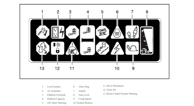
Platform control indicator panel for the articulated boom lift
1. Foot switch/enable indicator
When operating any function, the foot switch must be pressed and the function must be selected within 7 seconds. The authorization indicator light can display that the relevant control is authorized. If a function is not selected within 7 seconds, or if the interval between the end of a function and the start of the next function exceeds 7 seconds, the authorization indicator light will turn off, and the foot switch must be released and pressed again to authorize the relevant control.
Releasing the foot switch will disconnect all control power and activate the drive brake. To avoid serious injury, do not move, modify, or disable the foot switch through obstruction or other means. If the control function only takes effect when the foot switch reaches the last 1/4 inch of the top or bottom of the travel, the foot switch must be adjusted.
2. Engine malfunction indicator light
On the articulated boom lift before S/N 666888, when the power system of the articulated boom lift requires immediate maintenance, the indicator light will light up and the alarm will sound simultaneously.
Any of the following situations will cause the indicator light to light up and sound an alarm: low engine oil pressure; Engine coolant temperature too high; Engine air filter clogged; The generator output is too low; Hydraulic oil return filter clogged; Or the supply pump filter is blocked. On the curved arm aerial work vehicle from S/N 666888 to present, this indicator light shows that the engine control system has detected a fault and will write a diagnostic code into the system memory.
Please refer to the maintenance manual for the explanation and retrieval of fault codes. When the key switch is turned to the ON position, the fault indicator light will illuminate for 2-3 seconds to complete the self-test process.
3. Soft contact indicator light (if equipped)
When illuminated (yellow), it indicates that the soft contact bumper is in contact with an object. Before pressing the unlock button, all controls will be disabled. During this time, various controls can be operated in slow mode.
4. AC generator (green)
When lit (green), this indicator light indicates that the generator is working.
5. Low fuel level indicator light (yellow) (not applicable to liquefied propane)
When lit (yellow), it shows that there is only 1/8 or less fuel left in the fuel tank. When the indicator light is first lit, approximately 4 gallons of fuel remain available.
6. Load indicator light
Display the maximum platform load at the current position of the platform. Only restricted load capacity (shorter arm length and higher arm angle) is allowed in restricted platform positions
7. Slow speed indicator light
When the speed control of the function is turned to the slow position, this indicator light will light up (green) to remind that all functions have been set to the slowest speed.
8. Glow plug indicator light (if equipped)
When illuminated, it shows that the glow plug is working. After turning on the ignition switch, wait for the indicator light to turn off before starting the engine.
9. Tilt warning lights and alarms
The orange indicator light indicates that the chassis is on a slope. When the chassis is on a slope and the boom exceeds the horizontal position, the alarm will sound. If the indicator light is on when the boom is raised or extended, before continuing the operation, please retract and lower the boom to a position below the horizontal, and then reposition the articulated boom lift to make it horizontal.
If the boom is above the horizontal position and the curved arm high-altitude work vehicle is located on a slope, the tilt warning light will light up, and the alarm will sound and automatically switch to slow mode. If the tilt warning light is on when the boom is raised or extended, the boom should be retracted and lowered below the horizontal line, and then the curved arm aerial work vehicle should be repositioned to reach the horizontal level before the boom can be extended or raised above the horizontal position.
10. Overload indicator light (if equipped)
The display platform is overloaded.
11. Arm malfunction indicator light
When attempting to activate a tower arm function, if the alarm sounds and the boom malfunction indicator lights up, the function is being cut off by the tower arm limit switch. Under the current arm configuration, this function is disabled. If the alarm sounds and the boom malfunction indicator lights up without operating the boom or tower boom, the column is not aligned.
The articulated boom lift Operational Procedures
Generator startup steps
- Check the engine oil. If necessary, add engine oil according to the instructions in the engine manufacturer’s manual.
- Check the fuel level. Refuel if necessary.
- Check if the air filter assembly is in place and securely fixed.
- Install diesel engine models. After turning on the ignition switch, the operator should wait until the glow plug indicator light goes out (if equipped) before starting the engine.
- Turn the key of the selector switch to the ground position. Switch the power/emergency stop switch to on, then push the engine start switch upwards until the engine starts.
- After the engine is fully preheated, turn off the engine.
- Turn the key of the selector switch to the platform position.
- Switch the ‘power/emergency stop’ switch to ‘on’ from the platform position, then push the engine start switch forward until the engine starts.
Precautions for starting the generator
The initial start-up should always be carried out at the ground control station. If the engine fails to start properly, do not extend the start-up time. If the engine fails to start again, let the engine starter “cool down” for 2-3 minutes. Attempted multiple times but still failed, please refer to the engine maintenance manual. Before loading any load, let the engine warm up at low speed for a few minutes. Before the starter operates, the foot switch must be in the released (upper) position. If the starter operates with the foot switch in the pressed position, do not operate the articulated boom lift.
Generator shutdown steps
- Remove all loads and let the engine run at the low speed setting for 3-5 minutes. This can further reduce the internal temperature of the engine.
- Switch the power/emergency stop switch to the off position.
- Turn the key of the main control switch to the off position.
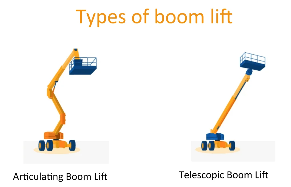
Articulated Boom Lift Types

TS-85 ft Articulating Boom Lift Electric
80ft Articulating Boom Lift, Diesel, Dual-Fuel

TS-60 ft Articulating Boom Lift, Diesel, Dual-Fuel
TS-60 ft Articulating Boom Lift Electric

TS-45 ft Articulating Boom Lift, Diesel, Dual-Fuel

TS-45 ft Articulating Boom Lift
The articulated boom lift Walking & Driving Procedures
Driving forward or backward
On the platform console, pull out the emergency stop switch, start the engine, and press the foot switch.
As needed, pull the “driving” control lever to the “forward” or “backward” position.
This curved arm high-altitude work vehicle is equipped with a driving directional indicator. The yellow indicator light on the platform console can indicate that the boom rotates beyond the rear drive wheel, and the driving/turning direction of the curved arm aerial work vehicle may be opposite to the control action direction. If the indicator lights up, please operate the drive function as follows:
Align the black and white directional arrows on the platform console and chassis to determine the direction of travel for the articulated boom lift.
Press and release the directional unlock switch for the drive within 3 seconds, and slowly move the drive control lever in the direction of the arrow that matches the predetermined travel direction of the articulated boom lift. In this within a 3-second interval, the indicator light will flash until the driver function is selected.
The articulated boom lift Walking & Driving Notices
Only on smooth, hard, and level ground can one drive with the upper arm above the horizontal line. To avoid driving out of control or overturning, do not allow the articulated boom lift to drive on longitudinal or lateral slopes that exceed the limit specified on the serial number nameplate.
Do not drive on slopes exceeding 5 degrees. Extreme caution should be exercised when driving in reverse or when the platform is raised. Before driving, align the black/white directional arrows on the chassis and platform console. Move the drive control handle in the direction corresponding to the directional arrow.
Turning operation of the articulated boom lift
Step on the foot switch and perform the steering operation. Push left to turn left; Push to the right to turn to the right.
Before operating the articulated boom lift, ensure that the upper arm is positioned beyond the rear axle. If the boom exceeds the front axle (steering wheel), the steering and driving control will be opposite to the direction of action of the articulated boom lift. The direction of the arrow label on the control handle will match the arrow label on the frame.
Parking and storage of curved arm high-altitude work vehicles
Park and store the articulated boom lift according to the following steps:
- Park the articulated boom lift in the driving position; The boom is lowered beyond the rear axle, all maintenance panels and doors are closed and locked, the ignition switch is turned off, and the turntable is locked.
- Check if the brakes can keep the articulated boom lift in position.
- Block the front and rear wheels.
- Turn the selector switch to the off position and remove the key.
Platform operation of the articulated boom lift
Loading from horizontal ground
Place the chassis on a smooth, hard, and level ground.
If the total load (personnel, tools, and materials) is less than the rated load, please evenly distribute the load on the platform floor and send it to the work location.
Loading from a position above the ground
When loading weight onto a platform above ground level:
Determine the total load capacity after loading the additional weight (personnel, tools, and materials).
If the total weight in the platform is less than the rated load, distribute the weight evenly on the platform floor.
Platform horizontal positioning
Level rise. Step on the foot switch, raise the platform, place the “Platform/Horizontal” control switch in the “Up” position and hold it down until the platform is level.
Horizontal decline. Step on the foot switch, lower the platform, place the “Platform/Horizontal” control switch in the “Lower” position and hold it down until the platform is level.
Platform positioning precautions
The platform leveling function can only be used for minor leveling of the platform. Incorrect use may cause the load or personnel to move or fall. Violating this warning may result in death or serious injury.
Platform rotation
When rotating the platform to the left or right, the platform rotation control switch can be used to select the corresponding direction and hold it until the desired position is reached.
Big arm operation of the articulated boom lift
Precautions when operating the boom:
When the chassis is on a steep slope, the orange tilt warning light on the console will illuminate. When illuminated, do not rotate, extend, or raise the boom beyond the horizontal position.
Do not use the tilt alarm as a level indicator for the chassis. Before rotating, extending or raising the tower arm beyond the horizontal position, the chassis must be level.
To avoid overturning, if the orange warning light is on when the boom extends or rises beyond the horizontal position, please retract and lower the platform close to the ground. Then reposition the machine to level the chassis before extending or raising the boom.
On longitudinal and lateral slopes not exceeding the slope indicated on the serial number nameplate, when the boom is retracted and below the level, it can be driven.
If any control lever or toggle switch that controls the platform action does not return to the OFF or neutral position after being released, to avoid serious injury, do not operate the machine.
To avoid collision and injury, if the platform does not stop after the control switch or control handle is released, please move your feet away from the foot switch or use the emergency stop switch to stop the machine.
Precautions for operating the articulated boom lift
Rotate the boom
Before starting any rotation operation, ensure that the turntable lock is disengaged. Press the foot switch. Turn the control switch or handle to the right or left and rotate the boom.
Lifting tower arm
The articulated boom lift has two control devices used to control the tower arms (two toggle switches), one to control the lifting of the tower arms, and the other to control the extension and retraction of the tower arms. The switch-switching system will sort its lifting and retracting functions as follows:
1. Step on the foot switch and sort the tower arm when lifting it from the fully lowered position.
- Before the tower arm can extend from the fully retracted position, it must be fully raised (approximately 12 degrees from the vertical direction).
- The tower arm extension function can only be operated when the tower arm is fully raised.
2. Step on the foot switch to lower the tower arm from the fully lowered position.
- The tower arm retracts. The tower arm must be fully retracted before it can be lowered.
- Only when the tower arm is fully retracted can the tower arm “lower” function be operated.
Lifting boom
When raising and lowering the boom, press the foot switch, place the boom lifting controller in the raised or lowered position, and hold it down until the desired height is reached.
Telescopic boom
When extending or retracting the boom, press the foot switch, place the boom extension control switch in the retracted or extended position, and hold it down until the platform reaches the desired position.
Tower arm function
The articulated boom lift has two control devices used to control the tower arms (two toggle switches), one to control the lifting of the tower arms, and the other to control the extension and retraction of the tower arms. The switch-switching system will sort its lifting and retracting functions as follows:
1. Sorting when raising the tower arm from the fully lowered position.
- Before the tower arm can extend from the fully retracted position, it must be fully raised (approximately 12 degrees from the vertical direction).
- Only when the tower arm is fully raised can the tower arm “extend” or “retract” function be operated.
2. Sorting when lowering the tower arm from the fully raised position.
- The tower arm retracts. The tower arm must be fully retracted before it can be lowered.
- Only when the tower arm is fully retracted can the tower arm “lower” function be operated.
Shutdown and parking of the articulated boom lift
- Drive the articulated boom lift into a protected area.
- Ensure that the boom is fully retracted and lowered above the rear (drive) shaft. All access panels and doors are closed and locked.
- Remove all loads and let the engine idle for 3-5 minutes to reduce the internal temperature of the engine.
- On the ground control device, switch the key selection switch to the (middle) ‘OFF’ position. Switch the power/emergency stop switch to the “OFF” position (below). Remove the key.
- Cover the platform console to protect the operation guide signs, warning labels, and operation control devices from adverse environments.
The above is an introduction to how to operate and use an articulated boom lift. It is quite simple. As long as we use it correctly according to the regulations, we can ensure the safe operation of the articulated boom lift, because correct operation can bring good results and benefits.